
It consists of a flattened, notched cylinder. Surrounding the main axis of the movement, an alignment pattern protrudes from the main body. This alignment will not only simplify the following modeling steps, but will also improve the usability of the clock_movement module as part of an OpenSCAD library. We decided to align the main body of the clock to the origin of the coordinate system in such a way that the surface of the main body is planar with the X-Y plane (displacement along the Z-axis by -height) and that later the axes of the clock movement will coincide with the Z-axis (displacement in X and Y direction by -width / 2 and -depth / 2). Even though our geometry description is not very extensive so far, we have already made an important design decision. Instead, we define them as variables within the module. Since we are modeling a given physical object, we can assume the measured quantities to be fixed and therefore do not need to make them parameters of the module. We start by defining a module and describing the box-shaped main body of the movement:
Openscad animation example how to#
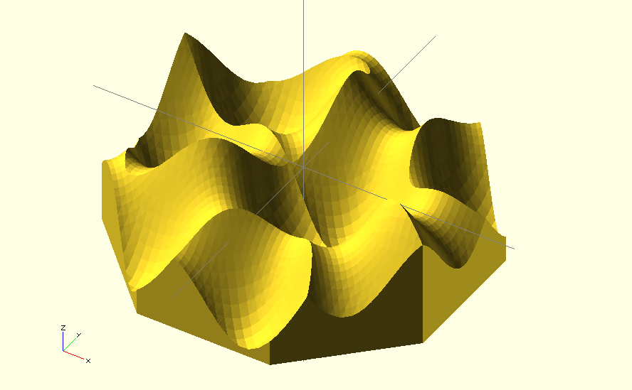
Furthermore we will use the search function and learn how to create simple animations with OpenSCAD. In terms of new transformations we will use mirror and resize. We will learn about the 2D basic shape import as well as the 3D basic shape surface. : A remodeled clock movement as a mockup What’s new? 🔗 As example, we will remodel a standard clock movement and design the geometry description in such a way that it can be comfortably used as part of an OpenSCAD library. In this project we want to take a closer look at important aspects that have to be considered if we want to create a useful OpenSCAD library. If you use certain components frequently, it is worth storing them in an OpenSCAD library and then including them in the respective project using include or use. This way, you can already see in the computer model whether all parts of the system really fit and are in the right place. In such cases, it is helpful to measure and remodel these components and use them as mockups in the geometry description. In the context of 3D printing, these are often motors, ball bearings, screws or nuts, for example.


When designing a technical system, it regularly happens that already existing components have to be integrated.


 0 kommentar(er)
